This document compiles the finite element analysis (FEA) setup variables, simulation load cases, and structural stress/deflection outcomes of the Smart Agri Four Legged Bot .
Simulations were performed using a solid tetrahedral mesh model in SolidWorks Simulation to represent both isotropic metals (mild steel) and anisotropic plastics (3D-printed PETG and PLA).
Mild Steel
Used For : Central chassis base, structural rib reinforcement platesYield Strength : 220–250 MPaYoung’s Modulus : 210 GPaPoisson’s Ratio : 0.30
PETG (FDM)
Used For : External covers, probe bracket, housing enclosuresYield Strength : 50 MPaYoung’s Modulus : 2.1 GPaPoisson’s Ratio : 0.38
PLA+ (FDM)
Used For : Leg joints, internal component base plate standoffsYield Strength : 60 MPaYoung’s Modulus : 3.2 GPaPoisson’s Ratio : 0.35
Rubber Pads
Used For : Sensor mounts, vibration dampersYield Strength : —Young’s Modulus : 0.01 GPaPoisson’s Ratio : 0.45
Element Type : SOLID187 (10-node quadratic tetrahedral element)Average Element Size : 5.0 mmMinimum Element Size : 1.0 mm (locally refined around bolt holes and corners)Average Aspect Ratio : < 3.5Mesh Quality : High (adaptive refinement active)
Three critical load cases representing the worst-case operating environments were simulated prior to fabrication.
graph LR
Chassis["Chassis Assembly"] --> Case1["Case 1: Vertical Gravity Load<br>98N downwards"]
Chassis --> Case2["Case 2: Lateral Bump Impact<br>30N side force"]
Chassis --> Case3["Case 3: Soil Probe Insertion<br>20N vertical resist"]
Case1 --> Res1["FOS: 5.17<br>Deflection: 0.313 mm"]
Case2 --> Res2["FOS: 2.04<br>Deflection: 3.600 mm"]
Case3 --> Res3["FOS: 14.40<br>Deflection: 0.780 mm"]
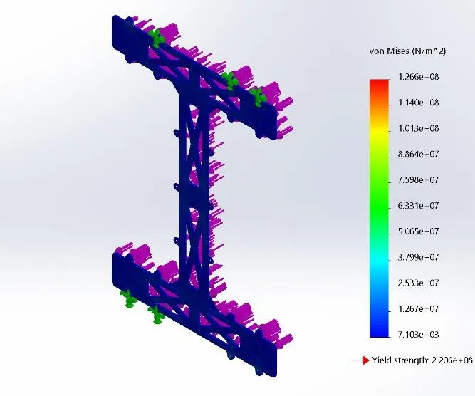
Physical Representation : Chassis fully loaded with electronics (approx. 10 kg total weight) resting stationary.Boundary Conditions : Fixed constraints at all 4 shoulder joints; a 98 N vertical downward force distributed on the chassis deck.Simulation Metrics :
Maximum Von Mises Stress : 42.58 MPaMaximum Deflection : 0.313 mm (located at the geometric center of the base plate)Maximum Strain : 1.238 × 10 − 4 1.238 \times 10^{-4} 1.238 × 1 0 − 4 Factor of Safety (FOS) : 5.17
Figure 3.19: Von Mises stress distribution — static vertical load
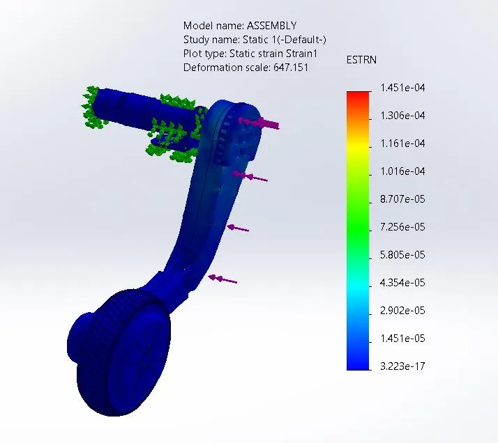
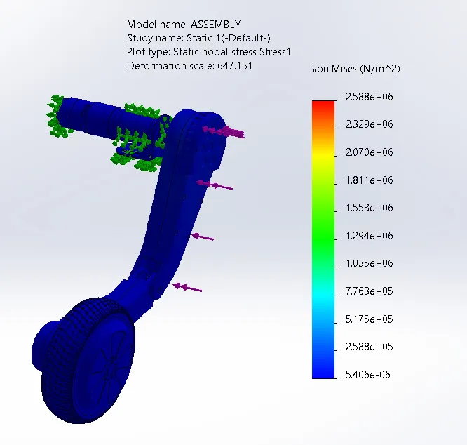
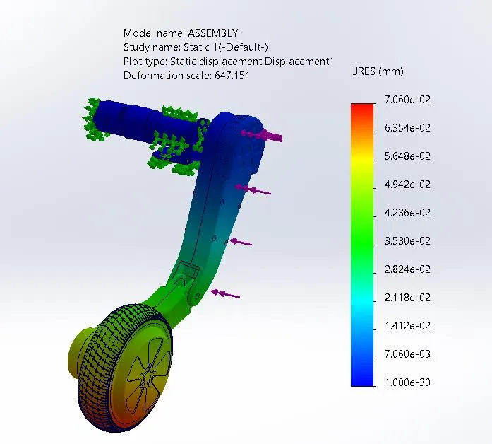
Physical Representation : A sudden bump or minor impact hitting one leg laterally during traversal.Boundary Conditions : Underside of the chassis fixed; a 30 N lateral side force applied directly to a leg mount.Simulation Metrics :
Maximum Von Mises Stress : 108.00 MPa (localized around the mounting flange bolt holes)Maximum Deflection : 3.60 mm (deflected in the lateral axis)Maximum Strain : 1.451 × 10 − 4 1.451 \times 10^{-4} 1.451 × 1 0 − 4 Factor of Safety (FOS) : 2.04
Figure 3.20: Strain under lateral load Figure 3.21: Von Mises stress under lateral load Figure 3.22: Displacement under lateral load
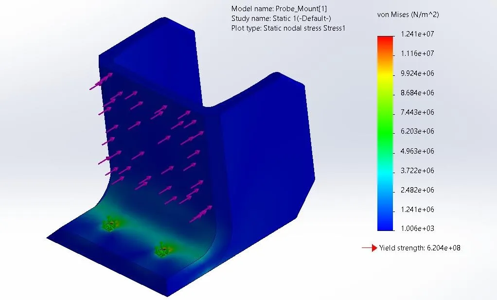
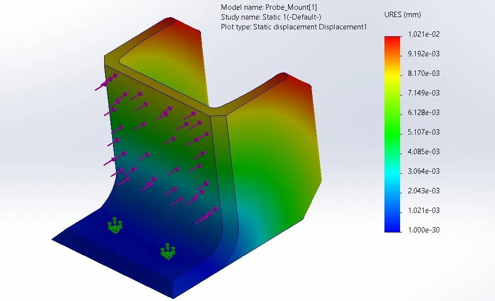
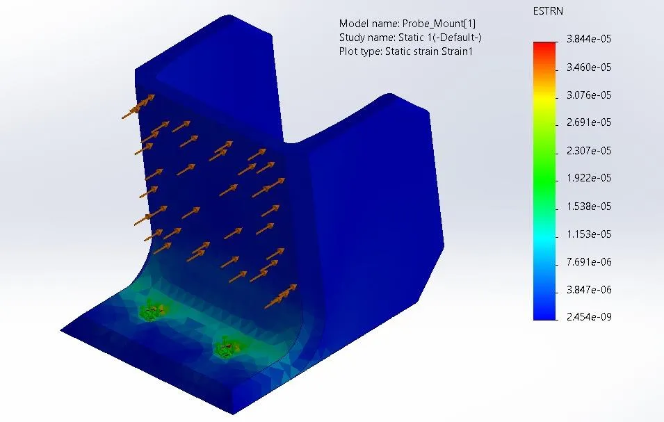
Physical Representation : Downward reaction force exerted by hard-packed loamy soil on the PETG mount during probe docking.Boundary Conditions : Rear enclosure attachment point fixed; 20 N vertical downward force acting at the probe bracket.Simulation Metrics :
Maximum Von Mises Stress : 43.00 MPa (localized at the bracket neck)Maximum Deflection : 0.78 mmMaximum Strain : 3.844 × 10 − 5 3.844 \times 10^{-5} 3.844 × 1 0 − 5 Factor of Safety (FOS) : 14.40 (designed with a high safety margin to resist cyclic fatigue)
Figure 3.23: Local stress concentration at probe clamp slot Figure 3.24: Vertical displacement of probe bracket under load Figure 3.25: Strain in probe bracket under load
Based on the FEA results, several structural optimizations were identified to improve future design revisions:
Leg-to-frame flange
Current Status : Single thickness plateSuggested Design Improvement : Add gusset plate or tapered transition to improve lateral bending resistance.
Probe mount neck
Current Status : Flat profile bracketSuggested Design Improvement : Integrate a curved fillet/radius at the neck region to further distribute localized stress.
Base ribs
Current Status : CNC-cut steel plateSuggested Design Improvement : Implement thickness reduction in non-critical zones to optimize overall weight.
Chassis cutouts
Current Status : Decorative X-pattern cutoutsSuggested Design Improvement : Add minor rounding to inner corners to lower localized stress spikes.