Skip to content

Mechanical Fabrication & Assembly

Material procurement, 3D printing configurations, physical assembly details, field correlation, and traversal testing.

This document compiles the physical fabrication specifications, assembly methods, field trials correlation, and mechanical testing results of the Smart Agri Four Legged Bot.


To bridge simulation and physical reality, the robot chassis base and key support links were fabricated through a hybrid approach combining metal laser cutting with FDM 3D printing.

The hybrid fabrication strategy mapped specific materials and manufacturing methods to their structural or environmental needs. Below is the responsive component breakdown:

Chassis Frame

  • Material: Mild Steel
  • Method: CNC cut + manual welding
  • Structural Justification: Main load-bearing frame; provides high yield strength and torque resistance under movement.

Reinforcement Plates

  • Material: Mild Steel
  • Method: CNC laser cut
  • Structural Justification: Provides added torsional stiffness and distributes leg forces across the base.

Shell Enclosures

  • Material: PETG (1.75 mm)
  • Method: FDM 3D Printed
  • Structural Justification: Lightweight cover; provides UV, heat, and moisture resistance under direct sunlight.

Wheel Mounts & Leg Joints

  • Material: PLA+
  • Method: FDM 3D Printed
  • Structural Justification: Distal leg linkage; high impact resistance and rigid structural support.

Probe Mount & Bracket

  • Material: PETG
  • Method: FDM 3D Printed
  • Structural Justification: Holds soil analysis probe; high fatigue life under cyclic insertion loads.

Electronics Base Plate

  • Material: PLA
  • Method: FDM 3D Printed
  • Structural Justification: Internal base; insulates electronics and routes cables cleanly with embedded anchors.

Wiring Accessories

  • Material: Copper + PVC
  • Method: Manual assembly
  • Structural Justification: Interconnects power rails and signal lines with EMI shielding.
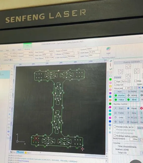
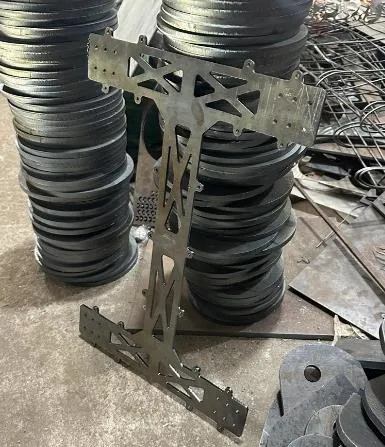
  • Chassis Plate: CNC laser-cut 3mm mild steel sheet, finished with anti-rust black primer and matte coating.
Chassis base loaded in laser cutting software
CNC Laser Cut Setup — chassis base in cutting software
Chassis base after laser cutting
Completed Chassis Plate — after laser cutting
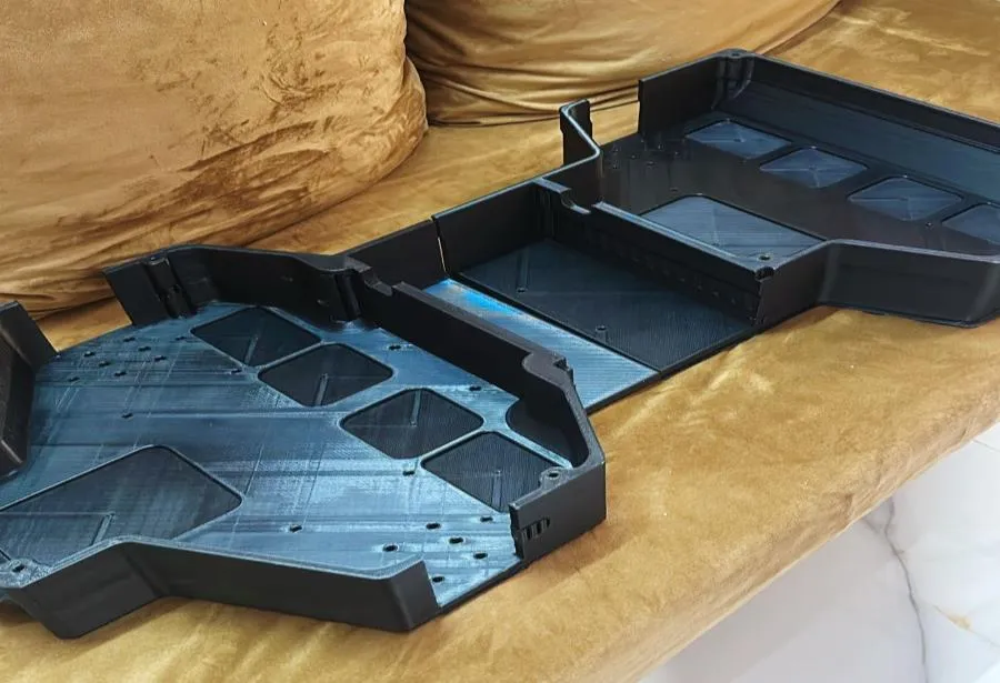
  • Venting & Enclosures: Interlocking PETG shells printed on an Elegoo Neptune 4 Max to contain motor drivers, regulators, and sensors.
  • Print Configuration Details:
    • Layer Height: 0.2 mm
    • Infill Density: 20%
    • Nozzle Temperature: 240°C
    • Bed Temperature: 60°C
    • Slicing Details: Ultimaker Cura slicer with brim support active to completely eliminate warping.
    • Local Reinforcements: Critical stress zones like screw bosses and cable pass-through slots were printed with increased wall thickness (2.4 mm) for extra durability.
3D printed upper shell parts
3D Printed Upper Enclosures
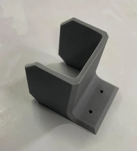
Probe mount and sensor housing printed
3D Printed Probe Bracket
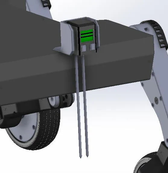
Probe mount CAD assembly
Probe Mount Assembly CAD

Modular Leg & Shoulder Actuator Assemblies

Section titled “Modular Leg & Shoulder Actuator Assemblies”
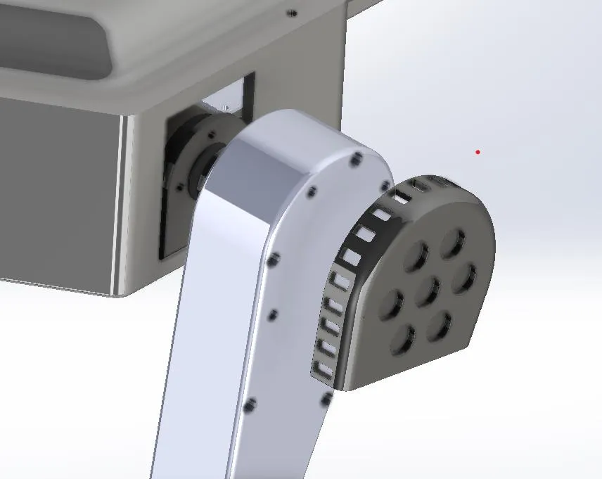
  • Shoulder Cap: Magnetically mounted shoulder enclosure with neodymium magnets for tool-less drive gear checks.
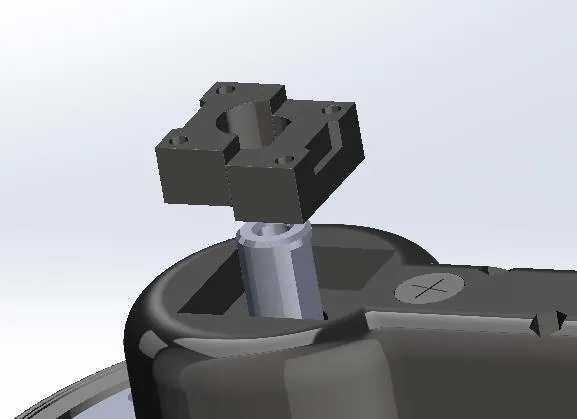
  • Distal Lock: 3D-printed split-piece locking block to lock the brushless hub wheel shaft firmly without adhesives.
Magnetically mounted shoulder cap enclosure
Magnetically Mounted Shoulder Cap
Split-piece locking block for hub wheel shaft
Locking Block & Leg Module

During the physical fabrication and calibration of the prototype, the team resolved several real-world engineering issues:

Leg Clearance Mismatch

  • Root Cause: Dimensional variation in raw hub motor shafts.
  • Solution Applied: Adjusted the CAD files with a small offset and reprinted the brackets.

PETG Warping in Large Prints

  • Root Cause: Bed adhesion failure due to uneven cooling.
  • Solution Applied: Added a print brim and optimized the chamber/cooling fan settings.

Motor Vibration & Fasteners

  • Root Cause: Cyclic resonance during drive motor tests.
  • Solution Applied: Applied Loctite thread locker and switched to Nylock nuts on critical fasteners.

After assembly, physical measurements were recorded using digital calipers and inclinometers during loaded trials to validate simulation accuracy.

Validation ParameterFEA Simulated ValueField Trial ObservationMatch status
Max Chassis Deflection (Static)0.313 mm0.31 mm99.0% Correlation
Stress at Leg Mount Joint (Static)42.58 MPaNo permanent deformationValid (No yielding)
Structural Fasteners IntegritySafeNo bolt loosening or shearValid (Nylock secure)
PETG Frame SofteningSafeStructural shape retainedValid (No warping)
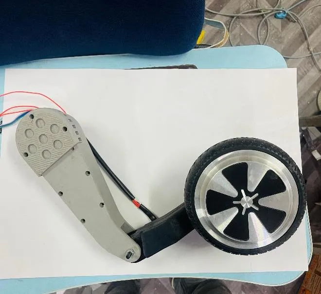
Completed leg module with Nylock fasteners
Figure 3.32: Completed leg module with Nylock fasteners

Field trials evaluated the chassis stability and the passive compliant spring joints in the legs across uneven loamy soil.

Before evaluating performance, the robot was tested under representative field conditions mirroring small-scale agricultural fields.

  • Test Area: 18 m × 12 m dry soil field.
  • Surface Profile: Uneven terrain with a slope up to 10° and elevation variance of ±4.2 cm.
Environmental ParameterValue / Range
Ambient Temperature31°C – 34°C
Soil Moisture Content13.2% (average)
Relative Humidity54% – 57%
Maximum Slope in Field~10°
Soil TextureLoamy-dry, cracked

The field testing plan was structured around validating the primary objectives:

  • Objective 1: Terrain-capable mechanical design
    • Validation Method: Motion over inclines and uneven terrain.
    • Quantifiable Result Status: Climbed ~9.8° slope stably; chassis tilt kept below 3.5°.
  • Objective 2: Structural integrity under loads
    • Validation Method: Frame deflection checks under live loads.
    • Quantifiable Result Status: Caliper verified maximum deflection of 0.31 mm (99.0% correlation with FEA).
  • Objective 3: Hybrid fabrication stability
    • Validation Method: Joint inspection post runtime.
    • Quantifiable Result Status: Joint geometry remained stable; no warping or fasteners failure.
  • Objective 4: ML-based real-time weed detection
    • Validation Method: Live Jetson Nano inference tests.
    • Quantifiable Result Status: Local CNN inference speed 9.2 FPS (stationary) and 5.0 FPS (traversal).
  • Objective 5: Sensor & electronics mounting
    • Validation Method: Vibration, heat, and fitment checks.
    • Quantifiable Result Status: Air-gapped ventilation grooves kept heatsinks and drivers safe.
  • Objective 6: System behavior under field stress
    • Validation Method: Combined endurance run (motion + thermal + data logging).
    • Quantifiable Result Status: Continuous 30-minute test run completed without any subsystem failure.
Surface ConditionSlope AngleChassis TiltPerformance Result
Forward Incline Climb~9.8°< 3.5°Stable traversal, no slip or rollback.
Lateral Path Bump±4.5 cm (step)MinimalCenter of gravity kept upright; spring compliant.
Soft Soil Trench~2.8 cm depthPassive correctionKnee linkage adjusted; frame remained level.
Path Obstacle (Stone)< 5.0 cm heightPassive correctionHub motor climbed smoothly; no path intervention.

5. Thermal Profiles Under Continuous Operation

Section titled “5. Thermal Profiles Under Continuous Operation”

The robot was run continuously for 30 minutes in direct sunlight at an average ambient temperature of 33.5°C. Temperatures were logged every 5 minutes using an infrared thermometer.
Monitored ZonePeak Recorded TempDesign ThresholdStatus
Jetson Nano Heatsink61.2°C80.0°CStable (Air-vent cooling effective)
Motor Driver PCB47.5°C75.0°CStable (No thermal throttling)
Li-ion Battery Pack38.2°C60.0°CStable (Safe operational margin)